
3D Printed Stirling Engine Project
This project was part of the Design and Proffesional Skills module. Each stuednt was provided with a Creality Ender 3 printer in whihc w had to assembel ourselves and print out the respective parts for a Stirling Engine. Below is a video showing each part of the Stirling Engine being printed. After this, the stirling engine was then assmebled and tested to see how long it could run for whilst on top of a single hot mug of water. The Stirling Engine works by cycling air between a hot and cold side using a displacer piston. When the air moves to the hot side it expands and pushes the power piston, and when it moves to the cold side it contracts and pulls it back. This repeating pressure change drives the crankshaft and flywheel, allowing the engine to spin continuously.
Arduino Based Stirling Engine Measurement Task
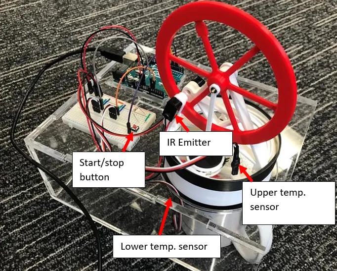
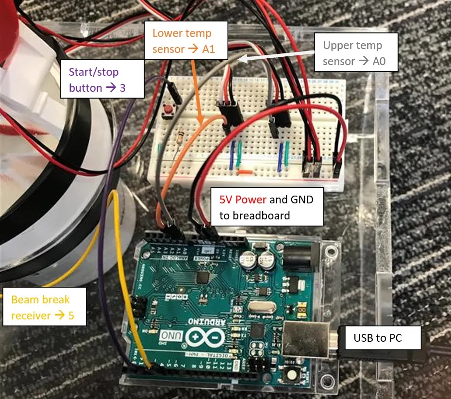
For this project, an Arduino-based Stirling engine was used to record a range of performance measurements. These included the temperature at the top of the engine, the temperature beneath the engine, and the temperature readings captured by a light-dependent sensor. The light sensor was used to determine the rotational speed of the flywheel by measuring the time taken for one of the six spokes to complete a full revolution. Angular velocity as a function of time was analysed, along with the overall efficiency of the engine. Two efficiency models were considered: the Carnot efficiency and the Chambadal–Novikov efficiency. A graph below presents the efficiency data obtained from the Stirling engine during analysis. The primary factors limiting efficiency were frictional losses—particularly at the piston rods—which could be reduced through improved lubrication, and air leakage, which lowers internal pressure and therefore performance. The full results and a step-by-step walkthrough of the project can be found in the Jupyter Notebook available for download below. Images of the experiment setup can also be seen below.

LVAC Impeller Manufacturing and Design Module Project
This module focused on designing an impeller based on client requirements. In my project, the brief was to design an impeller for an implantable ventricular assist device that had to fit within a 100 mm housing. I produced a full technical report documenting the entire design process, covering the following core areas:
- Problem Definition: Identification of functions, objectives (including an objective tree), and key constraints.
- Impeller Design Development: CAD models for multiple impeller concepts and derivation of key design parameters such as leading/trailing edge angles, inlet and outlet blade heights, and flow path geometry.
- Material Analysis & Selection: Definition of property constraints (e.g., stiffness, strength), derivation of Material Performance Indices (MPIs), and screening using Ashby plots generated in ANSYS EduPack.
- Manufacturing Method Selection: Comparative analysis considering capital cost, production rate, tool life, and geometric suitability. Closed-die forging was selected as the proposed manufacturing method.
- Sustainability Analysis: An Eco-Audit assessing material quantity, process impacts, mass, and end-of-life considerations.
I thoroughly enjoyed this project as it provided a holistic understanding of the multidisciplinary factors involved in engineering product development. It strengthened my knowledge of manufacturing processes and deepened my understanding of the considerations behind high-performance impeller design. I also gained experience using ANSYS EduPack—tools I later applied effectively during the IMechE Design Challenge. The final impeller was SLS-printed and tested using an industrial-grade pump, achieving an efficiency of approximately 35%. While this is relatively low, it is expected given that the prototype was printed in nylon rather than aluminium. Rendered images of the impeller, MPI comparison plots, the printed part and mounting assembly are shown below, and the full project report is available for download.

